
Adjustable hand-loaded storage
E-Z Rect Shelving
Two adjustable shelving styles for hand-loaded storage. Explore Type 1 and Trim Line, match an existing installation, or compare System 800 for a new shelving layout.
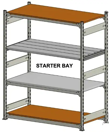
Medium to heavy-duty hand-loaded storage
E-Z Rect Type 1
A low-profile shelving system for stockrooms, warehouse picking areas and general industrial storage. Adjustable shelf levels and a choice of connectors and shelf surfaces let you specify the bay around the items you store.
- Shelf adjustment
- 2″ increments
- Post construction
- 12-gauge steel
- Standard finish
- Grey
- Layout options
- Starter and add-on bays
- Choose the shelf surface: wood, solid metal, sectional steel or wire decking, subject to configuration.
- Build a row: begin with a starter bay and extend with compatible add-on sections.
- Specify the details: shelf rests, locking clips, garment rods, footplates and back-panel options.
View Type 1 sizes & planning details
Common post heights: 48″, 60″, 72″, 84″, 96″, 108″, 120″, 132″ and 144″. Additional heights and cut-to-length posts can be discussed when quoting.
Listed end-frame depths: 12″, 15″, 16″, 18″, 24″, 30″, 36″, 42″ and 48″.
Listed connector widths include: 36″, 42″, 48″, 60″, 66″, 72″ and 96″. Widths vary by connector series; not every shelf surface is offered in every combination.
Type 1 also has specialized components for mezzanine and catwalk applications. These require project-specific design and engineering review, not a standard shelving-bay assumption.
All Type 1 parts, part numbers & sizes197 component and size entries · Browse or search the brochure reference
Type 1 component catalogue
Search or browse the manufacturer's March 2021 component guide. Current availability, order codes and compatibility are confirmed when quoted.
How to read part codes & sizes
“Series code” means you must also specify the size and finish. “Not listed” means the brochure does not supply a part number; use the component name and dimensions when contacting us. Dimensions are in inches and are nominal where indicated.
197 entries
Try a shorter code, a component name or another size. If your item is not listed, send us its details and we can help identify it.
Posts & post connectors 26 entries
Grey finish. Posts: 12-gauge, slots on 2″ centres; holes typically at 12″ intervals. Post connectors: 14-gauge with safety locking tab. Cut-to-length posts and welded-footplate options are listed; confirm the full configuration when ordering.
| Part / series code | Component | Size / configuration | Details |
|---|---|---|---|
| P 36 | Upright post | 36″ height | |
| P 48 | Upright post | 48″ height | |
| P 60 | Upright post | 60″ height | |
| P 72 | Upright post | 72″ height | |
| P 84 | Upright post | 84″ height | |
| P 96 | Upright post | 96″ height | |
| P 108 | Upright post | 108″ height | |
| P 120 | Upright post | 120″ height | |
| P 132 | Upright post | 132″ height | |
| P 144 | Upright post | 144″ height | |
| P 156 | Upright post | 156″ height | |
| P 168 | Upright post | 168″ height | |
| P 180 | Upright post | 180″ height | |
| P 192 | Upright post | 192″ height | |
| P 204 | Upright post | 204″ height | |
| P 216 | Upright post | 216″ height | |
| P 228 | Upright post | 228″ height | |
| PC 12 | Post connector | 12″ nominal end-frame depth | |
| PC 15 | Post connector | 15″ nominal end-frame depth | |
| PC 16 | Post connector | 16″ nominal end-frame depth | |
| PC 18 | Post connector | 18″ nominal end-frame depth | |
| PC 24 | Post connector | 24″ nominal end-frame depth | |
| PC 30 | Post connector | 30″ nominal end-frame depth | |
| PC 36 | Post connector | 36″ nominal end-frame depth | |
| PC 42 | Post connector | 42″ nominal end-frame depth | |
| PC 48 | Post connector | 48″ nominal end-frame depth |
Reference: E-Z Rect Type 1 component guide, March 1, 2021, page 1.
Frame connectors & tie bars 32 entries
Grey finish. Choose the connector series and shelf surface together; dimensions alone do not establish load capacity.
| Part / series code | Component | Size / configuration | Details |
|---|---|---|---|
| PBV 36 | PBV frame connector | 36″ nominal bay width | 13-gauge; 1⅛″ profile. |
| PBV 42 | PBV frame connector | 42″ nominal bay width | 13-gauge; 1⅛″ profile. |
| PBV 48 | PBV frame connector | 48″ nominal bay width | 13-gauge; 1⅛″ profile. |
| PBV 60 | PBV frame connector | 60″ nominal bay width | 13-gauge; 1⅛″ profile. |
| B 24 | B frame connector | 24″ nominal bay width | 13-gauge; 1⁵⁄₁₆″ profile. |
| B 36 | B frame connector | 36″ nominal bay width | 13-gauge; 1⁵⁄₁₆″ profile. |
| B 42 | B frame connector | 42″ nominal bay width | 13-gauge; 1⁵⁄₁₆″ profile. |
| B 48 | B frame connector | 48″ nominal bay width | 13-gauge; 1⁵⁄₁₆″ profile. |
| WB 36 | WB frame connector | 36″ nominal bay width | 13-gauge; 1⅞″ profile. |
| WB 42 | WB frame connector | 42″ nominal bay width | 13-gauge; 1⅞″ profile. |
| WB 48 | WB frame connector | 48″ nominal bay width | 13-gauge; 1⅞″ profile. |
| WB 60 | WB frame connector | 60″ nominal bay width | 13-gauge; 1⅞″ profile. |
| WB 66 | WB frame connector | 66″ nominal bay width | 13-gauge; 1⅞″ profile. |
| WB 72 | WB frame connector | 72″ nominal bay width | 13-gauge; 1⅞″ profile. |
| HD 36 | HD frame connector | 36″ nominal bay width | 12-gauge; 2⅜″ profile. |
| HD 48 | HD frame connector | 48″ nominal bay width | 12-gauge; 2⅜″ profile. |
| HD 60 | HD frame connector | 60″ nominal bay width | 12-gauge; 2⅜″ profile. |
| HD 72 | HD frame connector | 72″ nominal bay width | 12-gauge; 2⅜″ profile. |
| HD 96 | HD frame connector | 96″ nominal bay width | 12-gauge; 2⅜″ profile. |
| XHD 48 | XHD frame connector | 48″ nominal bay width | 12-gauge; 2⅜″ profile. |
| XHD 60 | XHD frame connector | 60″ nominal bay width | 12-gauge; 2⅜″ profile. |
| XHD 72 | XHD frame connector | 72″ nominal bay width | 12-gauge; 2⅜″ profile. |
| XHD 96 | XHD frame connector | 96″ nominal bay width | 12-gauge; 2⅜″ profile. |
| WT 12 | Combination tie bar / shelf support | 12″ nominal depth | 14-gauge. Fits WB and HD connectors. XHD requires a special WT; standard WT is not a confirmed match. |
| WT 15 | Combination tie bar / shelf support | 15″ nominal depth | 14-gauge. Fits WB and HD connectors. XHD requires a special WT; standard WT is not a confirmed match. |
| WT 16 | Combination tie bar / shelf support | 16″ nominal depth | 14-gauge. Fits WB and HD connectors. XHD requires a special WT; standard WT is not a confirmed match. |
| WT 18 | Combination tie bar / shelf support | 18″ nominal depth | 14-gauge. Fits WB and HD connectors. XHD requires a special WT; standard WT is not a confirmed match. |
| WT 24 | Combination tie bar / shelf support | 24″ nominal depth | 14-gauge. Fits WB and HD connectors. XHD requires a special WT; standard WT is not a confirmed match. |
| WT 30 | Combination tie bar / shelf support | 30″ nominal depth | 14-gauge. Fits WB and HD connectors. XHD requires a special WT; standard WT is not a confirmed match. |
| WT 36 | Combination tie bar / shelf support | 36″ nominal depth | 14-gauge. Fits WB and HD connectors. XHD requires a special WT; standard WT is not a confirmed match. |
| WT 42 | Combination tie bar / shelf support | 42″ nominal depth | 14-gauge. Fits WB and HD connectors. XHD requires a special WT; standard WT is not a confirmed match. |
| WT 48 | Combination tie bar / shelf support | 48″ nominal depth | 14-gauge. Fits WB and HD connectors. XHD requires a special WT; standard WT is not a confirmed match. |
Reference: E-Z Rect Type 1 component guide, March 1, 2021, page 2.
Footplates & shims 8 entries
Steel footplates are zinc-plated, 11-gauge. Matching steel shims are raw finish. Footplate footprint dimensions are not stated in the brochure.
| Part / series code | Component | Size / configuration | Details |
|---|---|---|---|
| STM | Single top-mounted footplate | Footprint not specified | Includes 5/16″ × 1¾″ Grade 5 bolt and nylon lock nut. |
| STM Shim | Shim for STM footplate | Not specified | Raw steel; confirm matching plate. |
| DTM | Double top-mounted footplate | Footprint not specified | Includes 5/16″ × 2½″ Grade 5 bolt and nylon lock nut. A longer bolt is required when X-bracing is used. |
| DTM Shim | Shim for DTM footplate | Not specified | Raw steel; confirm matching plate. |
| SM | Side-mounted footplate | Footprint not specified | Includes 5/16″ × 1¾″ Grade 5 bolt and nylon lock nut. |
| SM Shim | Shim for SM footplate | Not specified | Raw steel; confirm matching plate. |
| PFP | Polymer footplate | Not specified | High-impact black polymer. |
| PSS | Polymer stackable shim | Not specified | High-impact black polymer. Maximum four per post. |
Reference: E-Z Rect Type 1 component guide, March 1, 2021, page 3.
Shelf bars & garment storage 19 entries
Shelf bars and garment-rod supports are galvanized 18-gauge. Use two per level with four shelf rests or two connectors. Garment rods are galvanized 16-gauge, 1″ outside diameter.
| Part / series code | Component | Size / configuration | Details |
|---|---|---|---|
| SB 12 | Shelf bar | 12″ nominal depth | |
| SB 15 | Shelf bar | 15″ nominal depth | |
| SB 18 | Shelf bar | 18″ nominal depth | |
| SB 24 | Shelf bar | 24″ nominal depth | |
| SB 30 | Shelf bar | 30″ nominal depth | |
| SB 36 | Shelf bar | 36″ nominal depth | |
| SB 42 | Shelf bar | 42″ nominal depth | |
| SB 48 | Shelf bar | 48″ nominal depth | |
| GRS 12-1 | Garment rod support | 12″ nominal depth | 1 rod clip(s) standard; additional clips can be specified. |
| GRS 15-1 | Garment rod support | 15″ nominal depth | 1 rod clip(s) standard; additional clips can be specified. |
| GRS 18-1 | Garment rod support | 18″ nominal depth | 1 rod clip(s) standard; additional clips can be specified. |
| GRS 24-1 | Garment rod support | 24″ nominal depth | 1 rod clip(s) standard; additional clips can be specified. |
| GRS 30-2 | Garment rod support | 30″ nominal depth | 2 rod clip(s) standard; additional clips can be specified. |
| GRS 36-2 | Garment rod support | 36″ nominal depth | 2 rod clip(s) standard; additional clips can be specified. |
| GRS 42-2 | Garment rod support | 42″ nominal depth | 2 rod clip(s) standard; additional clips can be specified. |
| GRS 48-2 | Garment rod support | 48″ nominal depth | 2 rod clip(s) standard; additional clips can be specified. |
| GR 36 | Garment rod | 36″ length | 1″ outside diameter; 16-gauge galvanized tube. |
| GR 48 | Garment rod | 48″ length | 1″ outside diameter; 16-gauge galvanized tube. |
| GR 60 | Garment rod | 60″ length | 1″ outside diameter; 16-gauge galvanized tube. |
Reference: E-Z Rect Type 1 component guide, March 1, 2021, page 4.
Sectional shelves 14 entries
24-gauge sections, 6″ wide × 1¼″ high. The brochure gives finish series codes SSG and SSP plus lengths, not a separate full SKU for every length. Specify code, length and finish.
| Part / series code | Component | Size / configuration | Details |
|---|---|---|---|
| SSGSeries code | Galvanized sectional shelf | 36″ L × 6″ W × 1¼″ H | Series code; specify the listed length. |
| SSPSeries code | Painted sectional shelf | 36″ L × 6″ W × 1¼″ H | Series code; specify the listed length. |
| SSGSeries code | Galvanized sectional shelf | 42″ L × 6″ W × 1¼″ H | Series code; specify the listed length. |
| SSPSeries code | Painted sectional shelf | 42″ L × 6″ W × 1¼″ H | Series code; specify the listed length. |
| SSGSeries code | Galvanized sectional shelf | 48″ L × 6″ W × 1¼″ H | Series code; specify the listed length. |
| SSPSeries code | Painted sectional shelf | 48″ L × 6″ W × 1¼″ H | Series code; specify the listed length. |
| SSGSeries code | Galvanized sectional shelf | 60″ L × 6″ W × 1¼″ H | Series code; specify the listed length. |
| SSPSeries code | Painted sectional shelf | 60″ L × 6″ W × 1¼″ H | Series code; specify the listed length. |
| SSGSeries code | Galvanized sectional shelf | 66″ L × 6″ W × 1¼″ H | Series code; specify the listed length. |
| SSPSeries code | Painted sectional shelf | 66″ L × 6″ W × 1¼″ H | Series code; specify the listed length. |
| SSGSeries code | Galvanized sectional shelf | 72″ L × 6″ W × 1¼″ H | Series code; specify the listed length. |
| SSPSeries code | Painted sectional shelf | 72″ L × 6″ W × 1¼″ H | Series code; specify the listed length. |
| SSGSeries code | Galvanized sectional shelf | 96″ L × 6″ W × 1¼″ H | Series code; specify the listed length. |
| SSPSeries code | Painted sectional shelf | 96″ L × 6″ W × 1¼″ H | Series code; specify the listed length. |
Reference: E-Z Rect Type 1 component guide, March 1, 2021, page 5.
Solid metal shelves 28 entries
MSG is galvanized; MSP is painted. These are the series codes shown, not full size-specific SKUs. Specify depth × width, gauge and finish. Shelves without holes are available by specification.
| Part / series code | Component | Size / configuration | Details |
|---|---|---|---|
| MSGSeries code | Galvanized metal shelf | 12″ D × 36″ W | 20-gauge; series code, specify size and finish. |
| MSPSeries code | Painted metal shelf | 12″ D × 36″ W | 20-gauge; series code, specify size and finish. |
| MSGSeries code | Galvanized metal shelf | 15″ D × 36″ W | 20-gauge; series code, specify size and finish. |
| MSPSeries code | Painted metal shelf | 15″ D × 36″ W | 20-gauge; series code, specify size and finish. |
| MSGSeries code | Galvanized metal shelf | 18″ D × 36″ W | 20-gauge; series code, specify size and finish. |
| MSPSeries code | Painted metal shelf | 18″ D × 36″ W | 20-gauge; series code, specify size and finish. |
| MSGSeries code | Galvanized metal shelf | 24″ D × 36″ W | 20-gauge; series code, specify size and finish. |
| MSPSeries code | Painted metal shelf | 24″ D × 36″ W | 20-gauge; series code, specify size and finish. |
| MSGSeries code | Galvanized metal shelf | 12″ D × 48″ W | 20-gauge; series code, specify size and finish. |
| MSPSeries code | Painted metal shelf | 12″ D × 48″ W | 20-gauge; series code, specify size and finish. |
| MSGSeries code | Galvanized metal shelf | 15″ D × 48″ W | 20-gauge; series code, specify size and finish. |
| MSPSeries code | Painted metal shelf | 15″ D × 48″ W | 20-gauge; series code, specify size and finish. |
| MSGSeries code | Galvanized metal shelf | 18″ D × 48″ W | 20-gauge; series code, specify size and finish. |
| MSPSeries code | Painted metal shelf | 18″ D × 48″ W | 20-gauge; series code, specify size and finish. |
| MSGSeries code | Galvanized metal shelf | 24″ D × 48″ W | 20-gauge; series code, specify size and finish. |
| MSPSeries code | Painted metal shelf | 24″ D × 48″ W | 20-gauge; series code, specify size and finish. |
| MSGSeries code | Galvanized metal shelf | 18″ D × 36″ W | 18-gauge; series code, specify size and finish. |
| MSPSeries code | Painted metal shelf | 18″ D × 36″ W | 18-gauge; series code, specify size and finish. |
| MSGSeries code | Galvanized metal shelf | 24″ D × 36″ W | 18-gauge; series code, specify size and finish. |
| MSPSeries code | Painted metal shelf | 24″ D × 36″ W | 18-gauge; series code, specify size and finish. |
| MSGSeries code | Galvanized metal shelf | 30″ D × 36″ W | 18-gauge; series code, specify size and finish. |
| MSPSeries code | Painted metal shelf | 30″ D × 36″ W | 18-gauge; series code, specify size and finish. |
| MSGSeries code | Galvanized metal shelf | 18″ D × 48″ W | 18-gauge; series code, specify size and finish. |
| MSPSeries code | Painted metal shelf | 18″ D × 48″ W | 18-gauge; series code, specify size and finish. |
| MSGSeries code | Galvanized metal shelf | 24″ D × 48″ W | 18-gauge; series code, specify size and finish. |
| MSPSeries code | Painted metal shelf | 24″ D × 48″ W | 18-gauge; series code, specify size and finish. |
| MSGSeries code | Galvanized metal shelf | 30″ D × 48″ W | 18-gauge; series code, specify size and finish. |
| MSPSeries code | Painted metal shelf | 30″ D × 48″ W | 18-gauge; series code, specify size and finish. |
Reference: E-Z Rect Type 1 component guide, March 1, 2021, page 5.
Packing benches & caster options 14 entries
Packing/shipping benches use P 36 posts, the selected PC post connector, PSB members and four G floor plates. PSB identifies a member, not a complete bench SKU. Tops and lower shelves are specified separately.
| Part / series code | Component | Size / configuration | Details |
|---|---|---|---|
| PSB 66 | Packing / shipping bench member | 66″ length | |
| PSB 90 | Packing / shipping bench member | 90″ length | |
| Not listedNo code printed | Particleboard bench top / shelf configuration | Top: 24″ × 72″; lower shelf: 18″ × 66″ | Uses PC 18 and PSB 66. Dimensions are listed, but no complete bench or board SKU is supplied. |
| Not listedNo code printed | Particleboard bench top / shelf configuration | Top: 30″ × 72″; lower shelf: 24″ × 66″ | Uses PC 24 and PSB 66. Dimensions are listed, but no complete bench or board SKU is supplied. |
| Not listedNo code printed | Particleboard bench top / shelf configuration | Top: 36″ × 72″; lower shelf: 30″ × 66″ | Uses PC 30 and PSB 66. Dimensions are listed, but no complete bench or board SKU is supplied. |
| Not listedNo code printed | Particleboard bench top / shelf configuration | Top: 42″ × 72″; lower shelf: 36″ × 66″ | Uses PC 36 and PSB 66. Dimensions are listed, but no complete bench or board SKU is supplied. |
| Not listedNo code printed | Particleboard bench top / shelf configuration | Top: 48″ × 72″; lower shelf: 42″ × 66″ | Uses PC 42 and PSB 66. Dimensions are listed, but no complete bench or board SKU is supplied. |
| Not listedNo code printed | Particleboard bench top / shelf configuration | Top: 24″ × 96″; lower shelf: 18″ × 90″ | Uses PC 18 and PSB 90. Dimensions are listed, but no complete bench or board SKU is supplied. |
| Not listedNo code printed | Particleboard bench top / shelf configuration | Top: 30″ × 96″; lower shelf: 24″ × 90″ | Uses PC 24 and PSB 90. Dimensions are listed, but no complete bench or board SKU is supplied. |
| Not listedNo code printed | Particleboard bench top / shelf configuration | Top: 36″ × 96″; lower shelf: 30″ × 90″ | Uses PC 30 and PSB 90. Dimensions are listed, but no complete bench or board SKU is supplied. |
| Not listedNo code printed | Particleboard bench top / shelf configuration | Top: 42″ × 96″; lower shelf: 36″ × 90″ | Uses PC 36 and PSB 90. Dimensions are listed, but no complete bench or board SKU is supplied. |
| Not listedNo code printed | Particleboard bench top / shelf configuration | Top: 48″ × 96″; lower shelf: 42″ × 90″ | Uses PC 42 and PSB 90. Dimensions are listed, but no complete bench or board SKU is supplied. |
| Not listedNo code printed | Bolted-plate caster, swivel or rigid | 5″ caster | Supplied with mounting plate; welded plate-to-post connection and four 5/16″ × ¾″ bolts and nuts are described. Confirm assembly. |
| Not listedNo code printed | Bolted-plate swivel caster with brake | 5″ caster | Supplied with mounting plate; welded plate-to-post connection and four 5/16″ × ¾″ bolts and nuts are described. Confirm assembly. |
Reference: E-Z Rect Type 1 component guide, March 1, 2021, page 6.
Clips, caps, splices & accessories 9 entries
Where no size or distinct code is printed, identify the item by its name and confirm the required part when quoting.
| Part / series code | Component | Size / configuration | Details |
|---|---|---|---|
| EPS | External post splice | Not specified | Grey; bolts and nuts included. Specify seismic conditions or back-to-back posts. |
| IPS | Internal post splice | Not specified | Raw finish. |
| C | Shelf rest | Left-hand / right-hand | Zinc-plated. Four per shelf: two left and two right. Specify if side panels are used. |
| CLC | Connector locking clip | Not specified | Zinc-plated. |
| G | Floor plate | Not specified | Zinc-plated. |
| BTC | Top or bottom cap | Not specified | Black polymer. |
| Z | Tandem lock | Not specified | Zinc-plated. |
| Not listedNo code printed | Tandem bolt | Not specified | No separate code or dimensions printed. |
| Not listedNo code printed | Touch-up paint | Aerosol can; volume not specified | E-Z Rect grey or off-white; specify colour. |
Reference: E-Z Rect Type 1 component guide, March 1, 2021, page 7.
Mezzanine & catwalk connectors 22 entries
Grey finish. Specialized connectors require project-specific engineering and component selection; this reference does not authorize a mezzanine or catwalk design.
| Part / series code | Component | Size / configuration | Details |
|---|---|---|---|
| MHD 36 | MHD mezzanine / catwalk connector | 36″ nominal length | 13-gauge. Confirm application and engineering requirements. |
| MHD 48 | MHD mezzanine / catwalk connector | 48″ nominal length | 13-gauge. Confirm application and engineering requirements. |
| MHD 60 | MHD mezzanine / catwalk connector | 60″ nominal length | 13-gauge. Confirm application and engineering requirements. |
| MDHD 36 | MDHD mezzanine / catwalk connector | 36″ nominal length | 13-gauge. Confirm application and engineering requirements. |
| MDHD 48 | MDHD mezzanine / catwalk connector | 48″ nominal length | 13-gauge. Confirm application and engineering requirements. |
| MDHD 60 | MDHD mezzanine / catwalk connector | 60″ nominal length | 13-gauge. Confirm application and engineering requirements. |
| MXD 36 | MXD mezzanine / catwalk connector | 36″ nominal length | 12-gauge. Confirm application and engineering requirements. |
| MXD 48 | MXD mezzanine / catwalk connector | 48″ nominal length | 12-gauge. Confirm application and engineering requirements. |
| MXD 60 | MXD mezzanine / catwalk connector | 60″ nominal length | 12-gauge. Confirm application and engineering requirements. |
| CHDE 30 | CHDE mezzanine / catwalk connector | 30″ nominal length | 13-gauge. Confirm application and engineering requirements. |
| CHDE 36 | CHDE mezzanine / catwalk connector | 36″ nominal length | 13-gauge. Confirm application and engineering requirements. |
| CHDE 48 | CHDE mezzanine / catwalk connector | 48″ nominal length | 13-gauge. Confirm application and engineering requirements. |
| CHD 30 | CHD mezzanine / catwalk connector | 30″ nominal length | 13-gauge. Confirm application and engineering requirements. |
| CHD 36 | CHD mezzanine / catwalk connector | 36″ nominal length | 13-gauge. Confirm application and engineering requirements. |
| CHD 48 | CHD mezzanine / catwalk connector | 48″ nominal length | 13-gauge. Confirm application and engineering requirements. |
| CHD 60 | CHD mezzanine / catwalk connector | 60″ nominal length | 13-gauge. Confirm application and engineering requirements. |
| CDHD 36 | CDHD mezzanine / catwalk connector | 36″ nominal length | 13-gauge. Confirm application and engineering requirements. |
| CDHD 48 | CDHD mezzanine / catwalk connector | 48″ nominal length | 13-gauge. Confirm application and engineering requirements. |
| CDHD 60 | CDHD mezzanine / catwalk connector | 60″ nominal length | 13-gauge. Confirm application and engineering requirements. |
| CHB 30 | CHB mezzanine / catwalk connector | 30″ nominal length | 13-gauge. For cross-aisle tying and end-of-aisle handrail only. |
| CHB 36 | CHB mezzanine / catwalk connector | 36″ nominal length | 13-gauge. For cross-aisle tying and end-of-aisle handrail only. |
| CHB 48 | CHB mezzanine / catwalk connector | 48″ nominal length | 13-gauge. For cross-aisle tying and end-of-aisle handrail only. |
Reference: E-Z Rect Type 1 component guide, March 1, 2021, page 8.
Bay & end-frame bracing 14 entries
Brace straps: galvanized, 12-gauge × 1¾″ wide. Two straps make an X-brace, sized to cross at approximately 90°. Hardware included; specify single or back-to-back posts. Required bracing must be selected for the application.
| Part / series code | Component | Size / configuration | Details |
|---|---|---|---|
| BBS 36 | Bay brace strap | 36″ nominal bay size | |
| BBS 42 | Bay brace strap | 42″ nominal bay size | |
| BBS 48 | Bay brace strap | 48″ nominal bay size | |
| BBS 60 | Bay brace strap | 60″ nominal bay size | |
| BBS 66 | Bay brace strap | 66″ nominal bay size | |
| BBS 72 | Bay brace strap | 72″ nominal bay size | |
| BBS 96 | Bay brace strap | 96″ nominal bay size | |
| EBS 12 | End-frame brace strap | 12″ nominal end-frame size | Requires EFBB brace brackets. |
| EBS 18 | End-frame brace strap | 18″ nominal end-frame size | Requires EFBB brace brackets. |
| EBS 24 | End-frame brace strap | 24″ nominal end-frame size | Requires EFBB brace brackets. |
| EBS 30 | End-frame brace strap | 30″ nominal end-frame size | Requires EFBB brace brackets. |
| EBS 36 | End-frame brace strap | 36″ nominal end-frame size | Requires EFBB brace brackets. |
| EBS 48 | End-frame brace strap | 48″ nominal end-frame size | Requires EFBB brace brackets. |
| EFBB | End-frame brace bracket | Not specified | Galvanized 12-gauge. Quantity and use depend on engineering / special-condition requirements. |
Reference: E-Z Rect Type 1 component guide, March 1, 2021, page 9.
Back panels & aluminum holders 11 entries
The brochure specifies these by description and size without a distinct part number. Hardware package: 5/16″ × 1¾″ carriage bolts, 5/16″ flat washers and nylon lock nuts, plus #8 × ½″ square-head self-drilling screws.
| Part / series code | Component | Size / configuration | Details |
|---|---|---|---|
| Not listedNo code printed | Back-panel section | ½″ × 12″ × 36″ | Specify the panel size when quoting. |
| Not listedNo code printed | Back-panel section | ½″ × 12″ × 48″ | Specify the panel size when quoting. |
| Not listedNo code printed | Back-panel section | ½″ × 12″ × 60″ | Specify the panel size when quoting. |
| Not listedNo code printed | Back-panel section | ½″ × 12″ × 72″ | Specify the panel size when quoting. |
| Not listedNo code printed | Back-panel section | ½″ × 12″ × 96″ | Specify the panel size when quoting. |
| Not listedNo code printed | Aluminum back-panel holder | 48″ length | ½″ inside dimension for back-panel sections. |
| Not listedNo code printed | Aluminum back-panel holder | 60″ length | ½″ inside dimension for back-panel sections. |
| Not listedNo code printed | Aluminum back-panel holder | 72″ length | ½″ inside dimension for back-panel sections. |
| Not listedNo code printed | Aluminum back-panel holder | 84″ length | ½″ inside dimension for back-panel sections. |
| Not listedNo code printed | Aluminum back-panel holder | 96″ length | ½″ inside dimension for back-panel sections. |
| Not listedNo code printed | Aluminum back-panel holder | 120″ length | ½″ inside dimension for back-panel sections. |
Reference: E-Z Rect Type 1 component guide, March 1, 2021, page 10.
Codes shown here are not a compatibility or load-capacity guarantee. Tall shelving, bracing, mezzanine and catwalk components need application-specific review. Part dimensions are not shipping weights or load ratings.
Request Type 1 parts: send the code, size and quantity →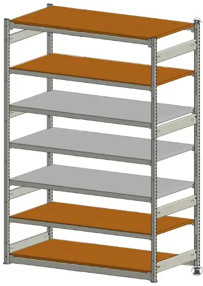
Light to medium-duty hand-loaded storage
E-Z Rect Trim Line
A low-profile shelving option for smaller items, supplies and retail backrooms. Closer shelf-height adjustment helps organize products of different heights, with accessories available for dividing or enclosing the storage space.
- Shelf adjustment
- 1″ increments
- Post construction
- 14-gauge steel
- Standard finish
- Off-white
- Layout options
- Starter and add-on bays
- Fine-tune shelf spacing: 1″ adjustment helps fit shelving levels around your inventory.
- Select your surface: metal or particleboard shelving, with sectional shelf options using the appropriate supports.
- Organize individual items: ask about dividers, side stops, panels and garment-storage accessories.
View Trim Line sizes & planning details
Common post heights: 48″, 60″, 72″, 84″, 96″, 108″, 120″, 132″ and 144″. Shorter posts and cut-to-length options can also be discussed.
Listed end-frame depths: 12″, 15″, 18″, 24″, 30″ and 36″.
Connector widths vary by style: 24″, 36″, 39½″ and 48″ in several standard connector styles; the TWB series also includes 60″, 66″ and 72″.
Listed solid-metal shelf sizes: 12″, 15″, 18″ or 24″ deep, in 36″, 39½″ or 48″ widths. Confirm the complete shelf and connector combination when requesting a quote.
Panel and accessory compatibility varies. Some side-panel configurations cannot be used with shelf bars, garment-rod supports or shelf clips; we will review your combination before ordering.
All Trim Line parts, part numbers & sizes208 component and size entries · Browse or search the brochure reference
Trim Line component catalogue
Search or browse the manufacturer's March 2021 component guide. Current availability, order codes and compatibility are confirmed when quoted.
How to read part codes & sizes
“Series code” means you must also specify the size and finish. “Not listed” means the brochure does not supply a part number; use the component name and dimensions when contacting us. Dimensions are in inches and are nominal where indicated.
208 entries
Try a shorter code, a component name or another size. If your item is not listed, send us its details and we can help identify it.
Posts, post connectors & tie bars 23 entries
Off-white, 14-gauge. Posts adjust on 1″ centres; where specified, holes are punched every 12″ for 5/16″ bolts. The brochure lists posts under 96″ without holes and 96″ or taller with holes; confirm current hole configuration. Cut lengths and welded-footplate options can be specified.
| Part / series code | Component | Size / configuration | Details |
|---|---|---|---|
| TP 24 | Upright post | 24″ height | |
| TP 36 | Upright post | 36″ height | |
| TP 48 | Upright post | 48″ height | |
| TP 60 | Upright post | 60″ height | |
| TP 72 | Upright post | 72″ height | |
| TP 84 | Upright post | 84″ height | |
| TP 96 | Upright post | 96″ height | |
| TP 108 | Upright post | 108″ height | |
| TP 120 | Upright post | 120″ height | |
| TP 132 | Upright post | 132″ height | |
| TP 144 | Upright post | 144″ height | |
| TPC 12 | Post connector | 12″ nominal end-frame depth | Safety locking tab. |
| TPC 15 | Post connector | 15″ nominal end-frame depth | Safety locking tab. |
| TPC 18 | Post connector | 18″ nominal end-frame depth | Safety locking tab. |
| TPC 24 | Post connector | 24″ nominal end-frame depth | Safety locking tab. |
| TPC 30 | Post connector | 30″ nominal end-frame depth | Safety locking tab. |
| TPC 36 | Post connector | 36″ nominal end-frame depth | Safety locking tab. |
| TCTB 12 | Combination tie bar / shelf support | 12″ nominal depth | Use with TWB frame connectors. |
| TCTB 15 | Combination tie bar / shelf support | 15″ nominal depth | Use with TWB frame connectors. |
| TCTB 18 | Combination tie bar / shelf support | 18″ nominal depth | Use with TWB frame connectors. |
| TCTB 24 | Combination tie bar / shelf support | 24″ nominal depth | Use with TWB frame connectors. |
| TCTB 30 | Combination tie bar / shelf support | 30″ nominal depth | Use with TWB frame connectors. |
| TCTB 36 | Combination tie bar / shelf support | 36″ nominal depth | Use with TWB frame connectors. |
Reference: E-Z Rect Trim Line component guide, March 1, 2021, page 1.
Frame connectors 18 entries
Off-white finish. Connector selection depends on shelf type and required loading; nominal width alone does not establish compatibility.
| Part / series code | Component | Size / configuration | Details |
|---|---|---|---|
| TFCL 24 | TFCL frame connector | 24″ nominal bay width | Use with TSC shelf clips and metal shelves. |
| TFCL 36 | TFCL frame connector | 36″ nominal bay width | Use with TSC shelf clips and metal shelves. |
| TFCL 39½ | TFCL frame connector | 39½″ nominal bay width | Use with TSC shelf clips and metal shelves. |
| TFCL 48 | TFCL frame connector | 48″ nominal bay width | Use with TSC shelf clips and metal shelves. |
| TFCV 24 | TFCV frame connector | 24″ nominal bay width | For particleboard shelves. |
| TFCV 36 | TFCV frame connector | 36″ nominal bay width | For particleboard shelves. |
| TFCV 39½ | TFCV frame connector | 39½″ nominal bay width | For particleboard shelves. |
| TFCV 48 | TFCV frame connector | 48″ nominal bay width | For particleboard shelves. |
| TBC 24 | TBC frame connector | 24″ nominal bay width | For use with TSC, particleboard or metal shelves. |
| TBC 36 | TBC frame connector | 36″ nominal bay width | For use with TSC, particleboard or metal shelves. |
| TBC 39½ | TBC frame connector | 39½″ nominal bay width | For use with TSC, particleboard or metal shelves. |
| TBC 48 | TBC frame connector | 48″ nominal bay width | For use with TSC, particleboard or metal shelves. |
| TWB 36 | TWB frame connector | 36″ nominal bay width | Listed for medium loads and kick-plate use; confirm the complete configuration. |
| TWB 39½ | TWB frame connector | 39½″ nominal bay width | Listed for medium loads and kick-plate use; confirm the complete configuration. |
| TWB 48 | TWB frame connector | 48″ nominal bay width | Listed for medium loads and kick-plate use; confirm the complete configuration. |
| TWB 60 | TWB frame connector | 60″ nominal bay width | Listed for medium loads and kick-plate use; confirm the complete configuration. |
| TWB 66 | TWB frame connector | 66″ nominal bay width | Listed for medium loads and kick-plate use; confirm the complete configuration. |
| TWB 72 | TWB frame connector | 72″ nominal bay width | Listed for medium loads and kick-plate use; confirm the complete configuration. |
Reference: E-Z Rect Trim Line component guide, March 1, 2021, page 2.
Metal shelves & shelf clips 13 entries
Solid shelves are off-white, 20-gauge. No distinct metal-shelf part number is printed in this brochure: order by depth × width and specify Trim Line. Other shelf sizes are noted as available on request, without listed dimensions.
| Part / series code | Component | Size / configuration | Details |
|---|---|---|---|
| Not listedNo code printed | Trim Line metal shelf | 12″ D × 36″ W | 20-gauge, off-white; no shelf SKU printed. |
| Not listedNo code printed | Trim Line metal shelf | 15″ D × 36″ W | 20-gauge, off-white; no shelf SKU printed. |
| Not listedNo code printed | Trim Line metal shelf | 18″ D × 36″ W | 20-gauge, off-white; no shelf SKU printed. |
| Not listedNo code printed | Trim Line metal shelf | 24″ D × 36″ W | 20-gauge, off-white; no shelf SKU printed. |
| Not listedNo code printed | Trim Line metal shelf | 12″ D × 39½″ W | 20-gauge, off-white; no shelf SKU printed. |
| Not listedNo code printed | Trim Line metal shelf | 15″ D × 39½″ W | 20-gauge, off-white; no shelf SKU printed. |
| Not listedNo code printed | Trim Line metal shelf | 18″ D × 39½″ W | 20-gauge, off-white; no shelf SKU printed. |
| Not listedNo code printed | Trim Line metal shelf | 24″ D × 39½″ W | 20-gauge, off-white; no shelf SKU printed. |
| Not listedNo code printed | Trim Line metal shelf | 12″ D × 48″ W | 20-gauge, off-white; no shelf SKU printed. |
| Not listedNo code printed | Trim Line metal shelf | 15″ D × 48″ W | 20-gauge, off-white; no shelf SKU printed. |
| Not listedNo code printed | Trim Line metal shelf | 18″ D × 48″ W | 20-gauge, off-white; no shelf SKU printed. |
| Not listedNo code printed | Trim Line metal shelf | 24″ D × 48″ W | 20-gauge, off-white; no shelf SKU printed. |
| TSC | Trim Line shelf clip | Left-hand / right-hand | Zinc-plated. Four per level: two left and two right. Specify if side panels are being used. |
Reference: E-Z Rect Trim Line component guide, March 1, 2021, page 2.
Shelf bars & garment storage 24 entries
Shelf bars and garment-rod supports: galvanized 18-gauge, two per level on shelf clips or frame connectors. TRB holders: galvanized 20-gauge. Rods: galvanized 16-gauge, 1″ outside diameter.
| Part / series code | Component | Size / configuration | Details |
|---|---|---|---|
| TSB 12 | Shelf bar | 12″ nominal depth | For sectional shelves. Sectional-shelf part numbers and sizes are not listed in the Trim Line brochure. |
| TSB 15 | Shelf bar | 15″ nominal depth | For sectional shelves. Sectional-shelf part numbers and sizes are not listed in the Trim Line brochure. |
| TSB 18 | Shelf bar | 18″ nominal depth | For sectional shelves. Sectional-shelf part numbers and sizes are not listed in the Trim Line brochure. |
| TSB 24 | Shelf bar | 24″ nominal depth | For sectional shelves. Sectional-shelf part numbers and sizes are not listed in the Trim Line brochure. |
| TSB 30 | Shelf bar | 30″ nominal depth | For sectional shelves. Sectional-shelf part numbers and sizes are not listed in the Trim Line brochure. |
| TSB 36 | Shelf bar | 36″ nominal depth | For sectional shelves. Sectional-shelf part numbers and sizes are not listed in the Trim Line brochure. |
| TGRS 12-1 | Garment rod support | 12″ nominal depth | 1 rod clip(s); additional clips can be specified. |
| TGRS 15-1 | Garment rod support | 15″ nominal depth | 1 rod clip(s); additional clips can be specified. |
| TGRS 18-1 | Garment rod support | 18″ nominal depth | 1 rod clip(s); additional clips can be specified. |
| TGRS 24-1 | Garment rod support | 24″ nominal depth | 1 rod clip(s); additional clips can be specified. |
| TGRS 30-2 | Garment rod support | 30″ nominal depth | 2 rod clip(s); additional clips can be specified. |
| TGRS 36-2 | Garment rod support | 36″ nominal depth | 2 rod clip(s); additional clips can be specified. |
| TRB 12 | Garment rod bracket / holder | 12″ nominal depth | Holes accept 1″ OD rod. Specify a rod ¾″ longer than the shelf width. |
| TRB 15 | Garment rod bracket / holder | 15″ nominal depth | Holes accept 1″ OD rod. Specify a rod ¾″ longer than the shelf width. |
| TRB 18 | Garment rod bracket / holder | 18″ nominal depth | Holes accept 1″ OD rod. Specify a rod ¾″ longer than the shelf width. |
| TRB 24 | Garment rod bracket / holder | 24″ nominal depth | Holes accept 1″ OD rod. Specify a rod ¾″ longer than the shelf width. |
| TRB 30 | Garment rod bracket / holder | 30″ nominal depth | Holes accept 1″ OD rod. Specify a rod ¾″ longer than the shelf width. |
| TRB 36 | Garment rod bracket / holder | 36″ nominal depth | Holes accept 1″ OD rod. Specify a rod ¾″ longer than the shelf width. |
| TGR 36 | Garment rod for TGRS | 36″ length | Use with TGRS garment-rod supports. |
| TGR 48 | Garment rod for TGRS | 48″ length | Use with TGRS garment-rod supports. |
| TGR 60 | Garment rod for TGRS | 60″ length | Use with TGRS garment-rod supports. |
| TGR 36¾ | Garment rod for TRB | 36¾″ length | Use with TRB garment-rod brackets. |
| TGR 48¾ | Garment rod for TRB | 48¾″ length | Use with TRB garment-rod brackets. |
| TGR 60¾ | Garment rod for TRB | 60¾″ length | Use with TRB garment-rod brackets. |
Reference: E-Z Rect Trim Line component guide, March 1, 2021, page 3.
Clips, caps & accessories 6 entries
| Part / series code | Component | Size / configuration | Details |
|---|---|---|---|
| TLC | Connector locking clip | Not specified | Zinc-plated. |
| TG | Floor plate | Not specified | Zinc-plated. |
| TTC | Top or bottom cap | Not specified | Black polymer. |
| TZ | Tandem lock | Not specified | Zinc-plated. |
| Not listedNo code printed | Tandem bolt | Not specified | No separate code or dimensions printed. |
| Not listedNo code printed | Touch-up paint | Aerosol can; volume not specified | E-Z Rect grey or off-white; specify colour. |
Reference: E-Z Rect Trim Line component guide, March 1, 2021, page 4.
White-board panels 6 entries
⅛″-thick white board. Panel dimensions are listed without a part number; match the panel width to the specified end-frame depth.
| Part / series code | Component | Size / configuration | Details |
|---|---|---|---|
| Not listedNo code printed | White-board panel | 12″ × 12⅞″ × ⅛″ thick | For 12″-deep end frame. |
| Not listedNo code printed | White-board panel | 12″ × 15⅞″ × ⅛″ thick | For 15″-deep end frame. |
| Not listedNo code printed | White-board panel | 12″ × 18⅞″ × ⅛″ thick | For 18″-deep end frame. |
| Not listedNo code printed | White-board panel | 12″ × 24⅞″ × ⅛″ thick | For 24″-deep end frame. |
| Not listedNo code printed | White-board panel | 12″ × 30⅞″ × ⅛″ thick | For 30″-deep end frame. |
| Not listedNo code printed | White-board panel | 12″ × 36⅞″ × ⅛″ thick | For 36″-deep end frame. |
Reference: E-Z Rect Trim Line component guide, March 1, 2021, page 4.
Polymer feet, leveling shims & post splices 5 entries
| Part / series code | Component | Size / configuration | Details |
|---|---|---|---|
| H | Floor plate / protector | Not specified | High-impact black polymer. |
| K | Stackable shim | Not specified | High-impact black polymer. |
| J | Steel leveling shim | 2″ outside diameter | Zinc-plated; used with H floor plate. |
| TEPS | External post splice | Not specified | Off-white; bolts and nuts included. Posts must be drilled to match TEPS. Specify seismic conditions or back-to-back posts. |
| TIPS | Internal post splice | Not specified | Raw finish. |
Reference: E-Z Rect Trim Line component guide, March 1, 2021, page 5.
Steel footplates & matching shims 6 entries
Zinc-plated 11-gauge steel footplates, with raw-steel matching shims. These use different listed bolt lengths from the Type 1 versions; identify the shelving style when ordering.
| Part / series code | Component | Size / configuration | Details |
|---|---|---|---|
| STM | Single top-mounted footplate | Footprint not specified | Includes 5/16″ × 1½″ Grade 5 bolt and nylon lock nut. |
| STM Shim | Shim for STM footplate | Not specified | Raw steel; confirm matching plate. |
| DTM | Double top-mounted footplate | Footprint not specified | Includes 5/16″ × 2″ Grade 5 bolt and nylon lock nut. A longer bolt is required with X-bracing. |
| DTM Shim | Shim for DTM footplate | Not specified | Raw steel; confirm matching plate. |
| SM | Side-mounted footplate | Footprint not specified | Includes 5/16″ × 1½″ Grade 5 bolt and nylon lock nut. |
| SM Shim | Shim for SM footplate | Not specified | Raw steel; confirm matching plate. |
Reference: E-Z Rect Trim Line component guide, March 1, 2021, page 6.
Bay & end-frame bracing 12 entries
Brace straps: galvanized, 12-gauge × 1¾″ wide. Two straps form an X-brace, sized to cross at approximately 90°. Hardware included. Specify single or back-to-back posts.
| Part / series code | Component | Size / configuration | Details |
|---|---|---|---|
| TBBS 36 | Bay brace strap | 36″ nominal bay size | |
| TBBS 39½ | Bay brace strap | 39½″ nominal bay size | |
| TBBS 48 | Bay brace strap | 48″ nominal bay size | |
| TBBS 60 | Bay brace strap | 60″ nominal bay size | |
| TBBS 66 | Bay brace strap | 66″ nominal bay size | |
| TBBS 72 | Bay brace strap | 72″ nominal bay size | |
| TEBS 12 | End-frame brace strap | 12″ nominal end-frame size | Requires EFBB brace brackets. |
| TEBS 18 | End-frame brace strap | 18″ nominal end-frame size | Requires EFBB brace brackets. |
| TEBS 24 | End-frame brace strap | 24″ nominal end-frame size | Requires EFBB brace brackets. |
| TEBS 30 | End-frame brace strap | 30″ nominal end-frame size | Requires EFBB brace brackets. |
| TEBS 36 | End-frame brace strap | 36″ nominal end-frame size | Requires EFBB brace brackets. |
| EFBB | End-frame brace bracket | Not specified | Galvanized 12-gauge; required to mount end-frame straps. Nuts and bolts included. |
Reference: E-Z Rect Trim Line component guide, March 1, 2021, page 7.
Side stops & side panels 23 entries
Off-white; listed as non-stock items in the brochure. Confirm lead time. TSP side panels cannot be used with shelf bars, garment-rod supports or shelf clips.
| Part / series code | Component | Size / configuration | Details |
|---|---|---|---|
| TSSSeries code | Side stop | 6″ × 12″ | Series code; specify size and whether fitted on shelf clips or connectors. |
| TSSSeries code | Side stop | 6″ × 15″ | Series code; specify size and whether fitted on shelf clips or connectors. |
| TSSSeries code | Side stop | 6″ × 18″ | Series code; specify size and whether fitted on shelf clips or connectors. |
| TSPSeries code | Side panel | 12″ D × 60″ H | Series code; specify size. Not for use with shelf bars, garment-rod supports or shelf clips. |
| TSPSeries code | Side panel | 15″ D × 60″ H | Series code; specify size. Not for use with shelf bars, garment-rod supports or shelf clips. |
| TSPSeries code | Side panel | 18″ D × 60″ H | Series code; specify size. Not for use with shelf bars, garment-rod supports or shelf clips. |
| TSPSeries code | Side panel | 24″ D × 60″ H | Series code; specify size. Not for use with shelf bars, garment-rod supports or shelf clips. |
| TSPSeries code | Side panel | 12″ D × 72″ H | Series code; specify size. Not for use with shelf bars, garment-rod supports or shelf clips. |
| TSPSeries code | Side panel | 15″ D × 72″ H | Series code; specify size. Not for use with shelf bars, garment-rod supports or shelf clips. |
| TSPSeries code | Side panel | 18″ D × 72″ H | Series code; specify size. Not for use with shelf bars, garment-rod supports or shelf clips. |
| TSPSeries code | Side panel | 24″ D × 72″ H | Series code; specify size. Not for use with shelf bars, garment-rod supports or shelf clips. |
| TSPSeries code | Side panel | 12″ D × 84″ H | Series code; specify size. Not for use with shelf bars, garment-rod supports or shelf clips. |
| TSPSeries code | Side panel | 15″ D × 84″ H | Series code; specify size. Not for use with shelf bars, garment-rod supports or shelf clips. |
| TSPSeries code | Side panel | 18″ D × 84″ H | Series code; specify size. Not for use with shelf bars, garment-rod supports or shelf clips. |
| TSPSeries code | Side panel | 24″ D × 84″ H | Series code; specify size. Not for use with shelf bars, garment-rod supports or shelf clips. |
| TSPSeries code | Side panel | 12″ D × 96″ H | Series code; specify size. Not for use with shelf bars, garment-rod supports or shelf clips. |
| TSPSeries code | Side panel | 15″ D × 96″ H | Series code; specify size. Not for use with shelf bars, garment-rod supports or shelf clips. |
| TSPSeries code | Side panel | 18″ D × 96″ H | Series code; specify size. Not for use with shelf bars, garment-rod supports or shelf clips. |
| TSPSeries code | Side panel | 24″ D × 96″ H | Series code; specify size. Not for use with shelf bars, garment-rod supports or shelf clips. |
| TSPSeries code | Side panel | 12″ D × 108″ H | Series code; specify size. Not for use with shelf bars, garment-rod supports or shelf clips. |
| TSPSeries code | Side panel | 15″ D × 108″ H | Series code; specify size. Not for use with shelf bars, garment-rod supports or shelf clips. |
| TSPSeries code | Side panel | 18″ D × 108″ H | Series code; specify size. Not for use with shelf bars, garment-rod supports or shelf clips. |
| TSPSeries code | Side panel | 24″ D × 108″ H | Series code; specify size. Not for use with shelf bars, garment-rod supports or shelf clips. |
Reference: E-Z Rect Trim Line component guide, March 1, 2021, page 8.
Back panels 20 entries
TBP is the series code, with sizes selected separately. Off-white; listed as non-stock. Panels hang from TBC or TWB connectors. For seismic applications, consult the manufacturer about bolt-on flat panels.
| Part / series code | Component | Size / configuration | Details |
|---|---|---|---|
| TBPSeries code | Back panel | 36″ W × 60″ H | Series code; specify size. Confirm connector and bay compatibility, particularly the listed 42″ panel. |
| TBPSeries code | Back panel | 39½″ W × 60″ H | Series code; specify size. Confirm connector and bay compatibility, particularly the listed 42″ panel. |
| TBPSeries code | Back panel | 42″ W × 60″ H | Series code; specify size. Confirm connector and bay compatibility, particularly the listed 42″ panel. |
| TBPSeries code | Back panel | 48″ W × 60″ H | Series code; specify size. Confirm connector and bay compatibility, particularly the listed 42″ panel. |
| TBPSeries code | Back panel | 36″ W × 72″ H | Series code; specify size. Confirm connector and bay compatibility, particularly the listed 42″ panel. |
| TBPSeries code | Back panel | 39½″ W × 72″ H | Series code; specify size. Confirm connector and bay compatibility, particularly the listed 42″ panel. |
| TBPSeries code | Back panel | 42″ W × 72″ H | Series code; specify size. Confirm connector and bay compatibility, particularly the listed 42″ panel. |
| TBPSeries code | Back panel | 48″ W × 72″ H | Series code; specify size. Confirm connector and bay compatibility, particularly the listed 42″ panel. |
| TBPSeries code | Back panel | 36″ W × 84″ H | Series code; specify size. Confirm connector and bay compatibility, particularly the listed 42″ panel. |
| TBPSeries code | Back panel | 39½″ W × 84″ H | Series code; specify size. Confirm connector and bay compatibility, particularly the listed 42″ panel. |
| TBPSeries code | Back panel | 42″ W × 84″ H | Series code; specify size. Confirm connector and bay compatibility, particularly the listed 42″ panel. |
| TBPSeries code | Back panel | 48″ W × 84″ H | Series code; specify size. Confirm connector and bay compatibility, particularly the listed 42″ panel. |
| TBPSeries code | Back panel | 36″ W × 96″ H | Series code; specify size. Confirm connector and bay compatibility, particularly the listed 42″ panel. |
| TBPSeries code | Back panel | 39½″ W × 96″ H | Series code; specify size. Confirm connector and bay compatibility, particularly the listed 42″ panel. |
| TBPSeries code | Back panel | 42″ W × 96″ H | Series code; specify size. Confirm connector and bay compatibility, particularly the listed 42″ panel. |
| TBPSeries code | Back panel | 48″ W × 96″ H | Series code; specify size. Confirm connector and bay compatibility, particularly the listed 42″ panel. |
| TBPSeries code | Back panel | 36″ W × 108″ H | Series code; specify size. Confirm connector and bay compatibility, particularly the listed 42″ panel. |
| TBPSeries code | Back panel | 39½″ W × 108″ H | Series code; specify size. Confirm connector and bay compatibility, particularly the listed 42″ panel. |
| TBPSeries code | Back panel | 42″ W × 108″ H | Series code; specify size. Confirm connector and bay compatibility, particularly the listed 42″ panel. |
| TBPSeries code | Back panel | 48″ W × 108″ H | Series code; specify size. Confirm connector and bay compatibility, particularly the listed 42″ panel. |
Reference: E-Z Rect Trim Line component guide, March 1, 2021, page 9.
Shelf dividers 32 entries
Off-white; listed as non-stock. SD is the shelf-divider code with dimensions; SDW is the single wrap-around alternative named in the brochure. Specify style and dimensions when quoting.
| Part / series code | Component | Size / configuration | Details |
|---|---|---|---|
| SD 6 × 12 | Shelf divider | 6″ H × 12″ D | Code and dimensions are shown together in the brochure. |
| SDWSeries code | Single wrap-around shelf divider | 6″ H × 12″ D | Series alternative to the listed SD size; confirm the full order code. |
| SD 6 × 15 | Shelf divider | 6″ H × 15″ D | Code and dimensions are shown together in the brochure. |
| SDWSeries code | Single wrap-around shelf divider | 6″ H × 15″ D | Series alternative to the listed SD size; confirm the full order code. |
| SD 6 × 18 | Shelf divider | 6″ H × 18″ D | Code and dimensions are shown together in the brochure. |
| SDWSeries code | Single wrap-around shelf divider | 6″ H × 18″ D | Series alternative to the listed SD size; confirm the full order code. |
| SD 6 × 24 | Shelf divider | 6″ H × 24″ D | Code and dimensions are shown together in the brochure. |
| SDWSeries code | Single wrap-around shelf divider | 6″ H × 24″ D | Series alternative to the listed SD size; confirm the full order code. |
| SD 8 × 12 | Shelf divider | 8″ H × 12″ D | Code and dimensions are shown together in the brochure. |
| SDWSeries code | Single wrap-around shelf divider | 8″ H × 12″ D | Series alternative to the listed SD size; confirm the full order code. |
| SD 8 × 15 | Shelf divider | 8″ H × 15″ D | Code and dimensions are shown together in the brochure. |
| SDWSeries code | Single wrap-around shelf divider | 8″ H × 15″ D | Series alternative to the listed SD size; confirm the full order code. |
| SD 8 × 18 | Shelf divider | 8″ H × 18″ D | Code and dimensions are shown together in the brochure. |
| SDWSeries code | Single wrap-around shelf divider | 8″ H × 18″ D | Series alternative to the listed SD size; confirm the full order code. |
| SD 8 × 24 | Shelf divider | 8″ H × 24″ D | Code and dimensions are shown together in the brochure. |
| SDWSeries code | Single wrap-around shelf divider | 8″ H × 24″ D | Series alternative to the listed SD size; confirm the full order code. |
| SD 10 × 12 | Shelf divider | 10″ H × 12″ D | Code and dimensions are shown together in the brochure. |
| SDWSeries code | Single wrap-around shelf divider | 10″ H × 12″ D | Series alternative to the listed SD size; confirm the full order code. |
| SD 10 × 15 | Shelf divider | 10″ H × 15″ D | Code and dimensions are shown together in the brochure. |
| SDWSeries code | Single wrap-around shelf divider | 10″ H × 15″ D | Series alternative to the listed SD size; confirm the full order code. |
| SD 10 × 18 | Shelf divider | 10″ H × 18″ D | Code and dimensions are shown together in the brochure. |
| SDWSeries code | Single wrap-around shelf divider | 10″ H × 18″ D | Series alternative to the listed SD size; confirm the full order code. |
| SD 10 × 24 | Shelf divider | 10″ H × 24″ D | Code and dimensions are shown together in the brochure. |
| SDWSeries code | Single wrap-around shelf divider | 10″ H × 24″ D | Series alternative to the listed SD size; confirm the full order code. |
| SD 12 × 12 | Shelf divider | 12″ H × 12″ D | Code and dimensions are shown together in the brochure. |
| SDWSeries code | Single wrap-around shelf divider | 12″ H × 12″ D | Series alternative to the listed SD size; confirm the full order code. |
| SD 12 × 15 | Shelf divider | 12″ H × 15″ D | Code and dimensions are shown together in the brochure. |
| SDWSeries code | Single wrap-around shelf divider | 12″ H × 15″ D | Series alternative to the listed SD size; confirm the full order code. |
| SD 12 × 18 | Shelf divider | 12″ H × 18″ D | Code and dimensions are shown together in the brochure. |
| SDWSeries code | Single wrap-around shelf divider | 12″ H × 18″ D | Series alternative to the listed SD size; confirm the full order code. |
| SD 12 × 24 | Shelf divider | 12″ H × 24″ D | Code and dimensions are shown together in the brochure. |
| SDWSeries code | Single wrap-around shelf divider | 12″ H × 24″ D | Series alternative to the listed SD size; confirm the full order code. |
Reference: E-Z Rect Trim Line component guide, March 1, 2021, page 9.
Wrap-around end panels 20 entries
WAEP is the series code; specify dimensions separately. Off-white; listed as non-stock. Confirm current availability and lead time.
| Part / series code | Component | Size / configuration | Details |
|---|---|---|---|
| WAEPSeries code | Wrap-around end panel | 12″ D × 60″ H | Series code; specify size. |
| WAEPSeries code | Wrap-around end panel | 15″ D × 60″ H | Series code; specify size. |
| WAEPSeries code | Wrap-around end panel | 18″ D × 60″ H | Series code; specify size. |
| WAEPSeries code | Wrap-around end panel | 24″ D × 60″ H | Series code; specify size. |
| WAEPSeries code | Wrap-around end panel | 30″ D × 60″ H | Series code; specify size. |
| WAEPSeries code | Wrap-around end panel | 12″ D × 72″ H | Series code; specify size. |
| WAEPSeries code | Wrap-around end panel | 15″ D × 72″ H | Series code; specify size. |
| WAEPSeries code | Wrap-around end panel | 18″ D × 72″ H | Series code; specify size. |
| WAEPSeries code | Wrap-around end panel | 24″ D × 72″ H | Series code; specify size. |
| WAEPSeries code | Wrap-around end panel | 30″ D × 72″ H | Series code; specify size. |
| WAEPSeries code | Wrap-around end panel | 12″ D × 84″ H | Series code; specify size. |
| WAEPSeries code | Wrap-around end panel | 15″ D × 84″ H | Series code; specify size. |
| WAEPSeries code | Wrap-around end panel | 18″ D × 84″ H | Series code; specify size. |
| WAEPSeries code | Wrap-around end panel | 24″ D × 84″ H | Series code; specify size. |
| WAEPSeries code | Wrap-around end panel | 30″ D × 84″ H | Series code; specify size. |
| WAEPSeries code | Wrap-around end panel | 12″ D × 96″ H | Series code; specify size. |
| WAEPSeries code | Wrap-around end panel | 15″ D × 96″ H | Series code; specify size. |
| WAEPSeries code | Wrap-around end panel | 18″ D × 96″ H | Series code; specify size. |
| WAEPSeries code | Wrap-around end panel | 24″ D × 96″ H | Series code; specify size. |
| WAEPSeries code | Wrap-around end panel | 30″ D × 96″ H | Series code; specify size. |
Reference: E-Z Rect Trim Line component guide, March 1, 2021, page 10.
Codes shown here are not a compatibility or load-capacity guarantee. Tall shelving, bracing, mezzanine and catwalk components need application-specific review. Part dimensions are not shipping weights or load ratings.
Request Trim Line parts: send the code, size and quantity →Our recommendation: compare before you choose
Starting fresh?
Take a look at System 800.
If you are planning a new warehouse or stockroom layout rather than matching existing E-Z Rect shelving, we recommend considering System 800 wide span shelving alongside it.
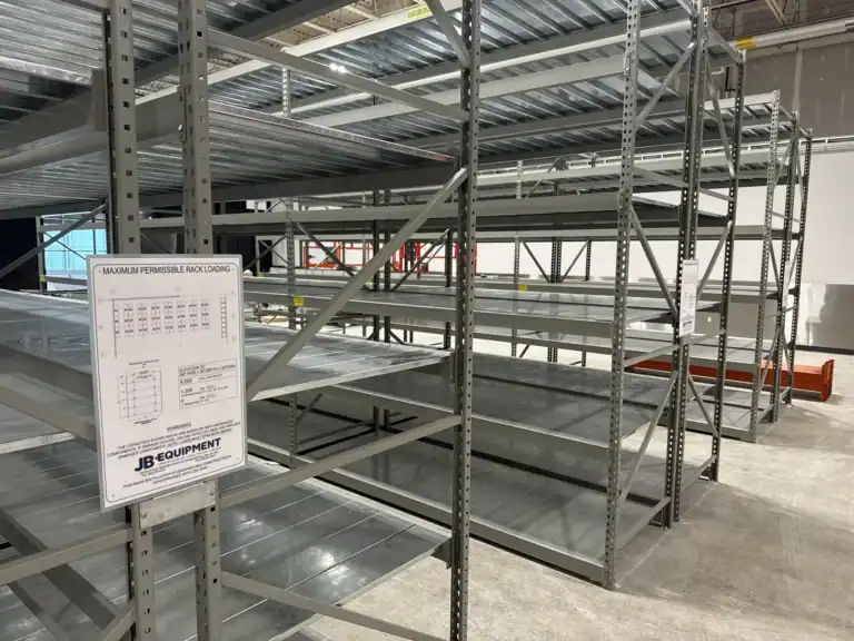
System 800 combines one-piece welded frames with adjustable step beams and a choice of shelf decking. It is a practical option to explore for hand-loaded cartons, bins and larger items.
- One-piece welded end frames with tubular bracing.
- 48″, 72″ and 96″ beam widths and 18″, 24″, 30″ and 36″ frame depths.
- Wire mesh, galvanized steel pans or wood decking to suit the application.
- 1½″ shelf-height adjustment for a flexible storage layout.
Prefer E-Z Rect? We can help with that too. Tell us what you are storing and whether you need to match an existing system.
At a glance
Which shelving system should you consider?
Start with the application and whether you are matching existing shelving. Then confirm dimensions, shelf surfaces and required capacity for the complete configuration.
Swipe the table to compare all three systems →
| Consideration | E-Z Rect Type 1 | E-Z Rect Trim Line | System 800 |
|---|---|---|---|
| A reason to consider it | Medium to heavy-duty hand-loaded applications or matching Type 1 | Light to medium-duty storage or matching Trim Line | A new wide span layout with welded end frames |
| Shelf-height adjustment | 2″ | 1″ | 1½″ |
| Frame construction | Posts assembled with post connectors | Posts assembled with post connectors | One-piece welded frames |
| Shelf surfaces | Wood, solid metal, sectional steel and wire options | Metal, particleboard and sectional shelf options | Wire mesh, galvanized steel pans and wood decking |
| Next step | View Type 1 | View Trim Line | Explore System 800 → |
Application descriptions are not load ratings. Capacity depends on the selected components, span, shelf surface, supports, loading and installation. Sizes, finishes, accessory compatibility and availability are confirmed when quoted. Components from different systems should not be mixed without verified compatibility.
Adding to what you already have?
Let’s identify your existing shelving first.
If you are expanding a row or replacing components, a few clear photos are the best starting point. Type 1 and Trim Line have different post and connector details, so a similar appearance alone is not enough to confirm a match.
Send us these details
- A photo of the full bay and any manufacturer labels.
- Close-ups of the post slots and shelf connections.
- Bay width, depth and overall height.
- Shelf surface, number of levels and the items being stored.
- Any visible part numbers and the quantity needed.
E-Z Rect shelving questions
What is the difference between Type 1 and Trim Line?
Type 1 is intended for medium to heavy-duty hand-loaded applications and adjusts on 2″ centres. Trim Line is intended for light to medium-duty hand-loaded applications and adjusts on 1″ centres. The systems use different posts and component selections; choose around the complete storage requirement rather than duty descriptions alone.
Should I choose E-Z Rect or System 800?
If you need to match existing E-Z Rect, start by identifying the style and components already installed. For a new layout, we recommend comparing System 800’s welded frames, beam widths and decking options with your E-Z Rect configuration. JB Equipment can help review both against the items you store and the space available.
Does boltless shelving mean no fasteners are needed?
The main shelving connections use an interlocking design, but some accessories, bracing, post splices and footplates use hardware. Floor anchoring and installation requirements must be reviewed for the particular layout and application.
Can I order a special height or different shelf configuration?
Cut-to-length posts and a variety of shelf and accessory configurations can be discussed when quoting. Send the dimensions, number of shelf levels and application so we can confirm a suitable combination and current availability.
How much weight can each shelf hold?
There is no single capacity that applies to every E-Z Rect shelf. The connector style, span, shelf material, supports and load distribution all matter. Tell us the expected load per shelf and what you are storing so the proposed configuration can be checked before purchase.
Plan your next shelving project
Tell us what you need to store.
Request E-Z Rect Type 1, Trim Line, or a comparison with System 800. Include your dimensions, shelf quantities, expected loads and delivery location so we can help specify your shelving.
Supply and installation in the GTA and Southern Ontario. Supply-only shipping across Canada.